Power Distribution Transformer Solutions
Engineering SupportGlobal Project Supply

How to Choose A Single Phase Pole Mounted Transformer?
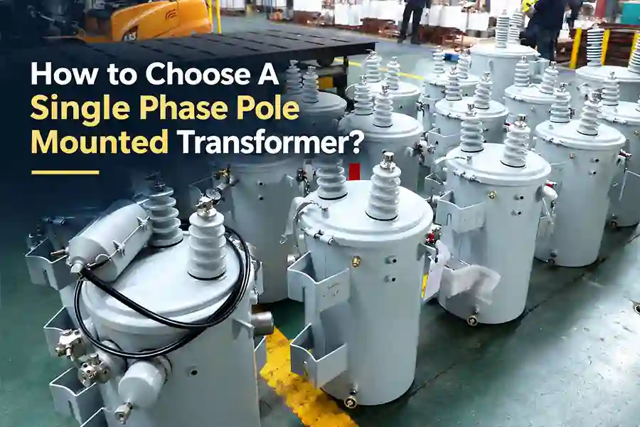
To choose the right single phase pole mounted transformer, you must verify eight technical. Checking circuit voltage, grid connection, winding voltage, kVA, secondary service, protection, core, site conditions, and standards.
Do not order from the system voltage alone. The stated grid voltage may differ from the voltage across the primary winding. Getting these specs right from the start. To keeps project costs low and stops tools from breaking down.
In the factory, I often encounter two common mistakes people make. First, customers often confuse the voltage on the primary winding with the overall grid voltage. Second, individuals utilize nameplate motor power or home counts to estimate kVA capacity.
Load type also matters. A transformer for homes may serve steady loads. A farm project may have large motor-starting currents. Different ratings could be required for these two projects. View china pole mounted transformer factory learn more.
What Should You Check Before Choosing?
Check these eight items before selecting a single-phase pole-mounted transformer.
Here is the exact checklist I review with our engineering team before quoting any overhead project:
① Distribution system and grounding:
Confirm if the line is a delta or grounded-wye layout.
② Actual primary winding voltage
Check the true voltage across the single-phase coil, not just the feeder nameplate.
③ Maximum demand and kVA
Size capacity using simultaneous peak load and motor starts rather than total connected watts.
④ Secondary voltage and wire configuration
Determine if you need a standard 120/240 V three-wire split-phase feed.
⑤ Conventional or CSP protection
Decide whether protection stays outside on the crossarm or inside the tank.
⑥ Core, winding, and loss requirements
Balance silicon steel or amorphous metal against your loading curve.
⑦ Installation environment
Account for site altitude, coastal salt fog, ambient heat, and lightning exposure.
⑧ Standards, tests, and documentation
Missing one item can change the final design. If you do not know an input, send the one-line diagram. A transformer engineer can review it before quotation.
What Distribution System and Application Will the Transformer Serve?
You should define the transformer requirements from electrical grid conditions and field application. Not a product catalog.
A 25 kVA unit is not automatically right for one house. A 50 kVA unit is not automatically right for two houses. Load behavior, system voltage, and utility rules must guide the decision.
Where Will the Single Phase Pole Transformer Actually Work?
The field application directly shapes your transformer kVA, protection hardware, and bushing layout.
- Single-family homes and small clusters: For home appliances, these loads require a reliable 120/240 V split-phase secondary.
- Rural power distribution: These long overhead lines often run phase-to-neutral and require strong lightning protection.
- Agricultural water pumps and light shop motors: Large motor inrush current causes severe voltage dip unless you size your kVA and impedance correctly.
- Light Commercial outbuildings: Retail spaces create steady daytime loads that need careful no-load and load loss balance.
- Utility replacement projects: Standard utility bids demand exact drop-in dimensions, lifting lugs, and matching basic insulation levels (BIL).
- Decentralized power taps: Off-grid spurs require robust sealed tanks that handle temperature swings with zero maintenance.
A residential project may need 120/240 V service. An agricultural project may have a high starting current. A utility project may require set bushing, BIL, and protection designs. Review About residential and urban distribution solutions.
What Project Information Should You Collect First?
You need twelve baseline project details before an engineer can design a reliable pole unit.
| Required Input | Why It Matters for Design |
| Nominal system voltage | Tells us the overall feeder voltage class. |
| Grounding method | Decides if you need one or two primary bushings. |
| Operating frequency | 50 Hz and 60 Hz cores use different steel amounts to avoid magnetic saturation. |
| Required secondary service | Determines coil tapping, such as 120/240 V three-wire output. |
| Maximum demand | Prevents transformer sizing mistakes and excessive tank heat. |
| Motor starting current | Determines short-time overload capability and required percent impedance. |
| Ambient temperature | Dictates winding temperature rise limits (typically 55°C or 65°C). |
| Installation altitude | Sites over 1,000 meters (3,300 feet) suffer poorer air cooling and need insulation derating. |
| Applicable standard | Decides clearance, test voltages, and hardware compliance rules. |
| Destination country | Sets shipping constraints, Shipping fee and time. |
Remember to keep system voltage and primary winding voltage separate. They are rarely the same number on rural single-phase taps.
How Do You Match the Primary Voltage to the Grid?
Match primary voltage by identifying the exact electrical connection between transformer winding and the overhead phase wires.
Getting this step wrong burns up windings on energization. Many buyers give us an overall line voltage when their transformer actually hangs across a phase wire and a grounded neutral.
What Is the Difference Between Line-to-Line and Phase-to-Neutral Voltage?
A grounded-wye system has different line-to-line and phase-to-neutral voltages.
Line-to-line voltage is measured between two phase conductors. Phase-to-neutral voltage is measured from one phase to the neutral point.
For a balanced grounded-wye system:
Phase-to-neutral voltage = line-to-line voltage ÷ √3
V(L–N) = V(L–L) ÷ √3
For a 12.47 kV grounded-wye feeder:
12.47 kV ÷ √3 = 12.47 kV ÷ 1.732 ≈ 7.20 kV
The grid is called a 12.47 kV system. Yet a phase-to-neutral primary winding may receive about 7.2 kV. If you accidentally order a 12.47 kV rated coil for that connection. the unit runs severely under-fluxed and outputs incorrect secondary voltage.
Do not select the primary rating from the line-to-line voltage alone. Submit the system connection diagram when the winding voltage is uncertain.
How Does Grounding Affect Your Primary Bushings?
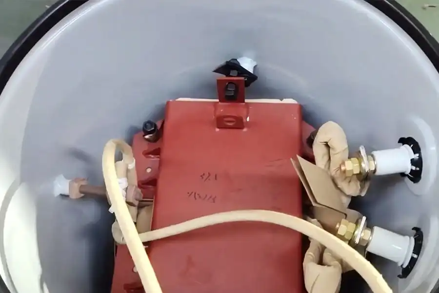
The grid grounding setup directly dictates connection determine the required bushing arrangement. One or two high-voltage bushing.
Some single-phase pole transformers use one high-voltage bushing. Others use two. The choice depends on the system connection, grounding method, and utility specification.
H1 and H2 are common primary-terminal labels. They do not, by themselves, tell you how every unit should connect.
The current conventional product example shows two high-voltage bushings. That is one available arrangement. It is not a rule for every pole-mounted transformer.
Our factory often showcase pole-mounted units with two high-voltage bushings. Because that conventional build offers flexible field connections.
Never use a general blog article as a field wiring instruction. Qualified workers must follow approved drawings and local procedures. In the United States, OSHA 1910.269 covers work on electric power systems.
How Do You Select the Right kVA Capacity?
Choose kVA from maximum demand, load behavior, and future needs. Rather than simply adding up the wattage of all your appliances.
An undersized single-phase pole-mount transformer overheats, trips fuses, and suffers rapid oil degradation. An oversized unit costs more and may raise fixed no-load losses.
How Do You Calculate the Load?
Use maximum operating demand because electrical equipment rarely runs all at once.
The basic single-phase apparent-power formula is:
kVA = (V × I) ÷ 1,000
This formula is only the starting point. Also check:
- Maximum simultaneous demand
- Diversity between connected loads
- Continuous and short-time loads
- Motor-starting current
- Cyclic loads
- Expected future expansion
- Secondary voltage drop
- Utility loading rules
Do not add a fixed 20% margin to every project. Some projects may need less. Others may need more. The decision depends on load behavior and the accepted temperature limits.
See Related Atricle: Single-Phase Transformer Sizing Fundamentals.
When Should You Choose 25 kVA Instead of 50 kVA?
Choose 25 kVA single phase pole mounted transformer for small residential services with standard baseloads. Choose 50 kVA for larger properties running central cooling and heavy pump motors.
| Consideration | 25 kVA may fit when | 50 kVA may fit when |
|---|---|---|
| Peak demand | Calculated maximum load stays under 22 kW. | Peak load regularly exceeds 25 kW to 40 kW. |
| Motor loads | Starting current is limited | Larger motors create high inrush |
| Future growth | Little load growth is expected | New loads are already planned |
| Utility rules | Utility policy permits 100% to 120% cyclic peak loading. | Local grid rules enforce strict nameplate limits. |
A 25 kVA transformer may serve a light residential load. However, that does not create a universal “homes per transformer” rule.
Send the expected peak load and motor data to Huasheng Experts. An engineer can then verify whether 25 kVA, 50 kVA, or another rating fits.
What Are the Typical Factory kVA Configurations?
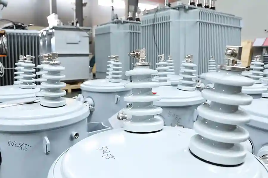
Manufacturers build single-phase pole mounted transformers across standardized ratings ranging from 5 kVA up to 167 kVA.
Available ratings depend on the primary voltage, core design, and project standard. Common industrial capacities include:
- Silicon Steel (CRGO) Cores: Standard production covers 15, 25, 37.5, 50, 75, 100, and 167 kVA for medium-voltage taps such as 7.97 kV and 19.92 kV.
- Amorphous Metal Cores: Typical setups range from 5 to 167 kVA on lower primary taps like 7.62 kV, and 10 to 75 kVA on higher voltage lines like 14.4 kV.
Should You Choose a Conventional or CSP Transformer?
Choose the protection plan first, then decide where each protective device belongs.
Conventional and completely self-protected transformers use different protection arrangements. Neither design is automatically right for every grid.
When Is a Conventional (CON) Transformer the Better Choice?
A conventional transformer is ideal when local line crews prefer working on external crossarm cutouts and surge arresters.
CON type units use a simple, robust construction. They leave primary fusing and surge suppression to external pole-top devices:
- External primary fuse cutout
- Pole-mounted surge arresters
- Simple internal build
- Secondary protection
- Utility maintenance practices
If your line workers carry replacement fuse links on their service trucks, conventional units keep tank costs low and maintenance procedures familiar.
When Is a CSP Transformer Preferred?
A CSP may fit projects that need more protection inside the transformer package.
CSP means completely self-protected. Depending on the design, it may include an internal fuse, secondary breaker, or surge protection.
Always specify the exact accessories you need. Do not just ask for “CSP” and assume every model includes an internal breaker. Define the protection philosophy first, and then specify which protection functions must be external or integrated.
A useful rule is:
Choose the protection plan first. Then state which functions must be external or integrated.
This prevents differences between the buyer’s request and the supplier’s proposal.
How Do You Choose the Core, Windings, and Insulating Oil?
Choose core and winding materials by evaluating long-term electrical losses, total unit weight, and equipment cost.
No single material wins every project. Core material affects losses. Yet it does not work alone. Winding design, primary voltage, temperature rise, and loading also affect performance.
If your transformer sits idle for ten months out of the year. A copper winding or an ultra-low-loss core is not automatically the smartest choice.
How Do CRGO and Amorphous Cores Differ?
CRGO is a common core steel, while amorphous alloy often reduces no-load loss.
Cold-rolled grain-oriented (CRGO) electrical steel has served as the industry standard for decades. It offers high magnetic saturation limits, compact core footprints.
Amorphous alloy uses a thin metallic ribbon. Its magnetic structure can reduce no-load loss. This may help when a transformer stays energized for long periods.
However, no-load loss is only one part of the decision.
A high-load project must also consider load loss. Buyers should compare size, weight, sound, purchase cost, and loss guarantees.
I do not select an amorphous core from one low-loss number. I first ask how the transformer will load each day.
Examining following table data across typical capacities. To learn how core material changes losses, primary voltage taps, and overall physical weight.
| Rating | Core | Primary voltage | No-load loss | Full-load loss | Oil weight | Total weight |
|---|---|---|---|---|---|---|
| 25 kVA | CRGO | 7.97 kV | 73 W | 240 W | 68 kg | 231 kg |
| 25 kVA | Amorphous | 7.62 kV | 18 W | 290 W | 41 kg | 215 kg |
| 37.5 kVA | CRGO | 7.97 kV | 101 W | 331 W | 86 kg | 288 kg |
| 37.5 kVA | Amorphous | 7.62 kV | 30 W | 360 W | 52 kg | 270 kg |
| 50 kVA | CRGO | 7.97 kV | 115 W | 430 W | 96 kg | 337 kg |
| 50 kVA | Amorphous | 7.62 kV | 32 W | 500 W | 66 kg | 318 kg |
| 75 kVA | CRGO | 7.97 kV | 152 W | 600 W | 114 kg | 425 kg |
| 75 kVA | Amorphous | 7.62 kV | 45 W | 650 W | 86 kg | 440 kg |
Three points stand out:
- The amorphous samples show about 70% to 75% lower no-load loss.
- Their listed full-load loss is about 8% to 21% higher.
- Their total weight is not always lower.
The CRGO samples use a 7.97 kV primary and +1/−3 × 2.5% taps. The amorphous samples use 7.62 kV and ±2 × 2.5% taps.
These differences matter. They prevent a strict material-only comparison.
Send the expected load factor and annual operating hours. These inputs help identify the better core option.
Huasheng as a Chinese Transformer Manufacturer. We can provide you with CRGO and amorphous alloy design solutions.
Should You Choose Copper or Aluminum Windings?
Copper saves physical space and weight. while aluminum cuts manufacturing costs while matching electrical performance when properly sized.
| Factor | What to compare |
|---|---|
| Conductivity | Required conductor size and resistance |
| Weight | Total active-part and unit weight |
| Thermal design | Heat rise at the required load |
| Mechanical design | Strength during transport and faults |
| Cost | Material and finished-unit price |
| Specification | Mandatory tender requirements |
Copper is not automatically better in every design. Aluminum is not automatically a low-quality choice.
Ask for guaranteed losses, temperature-rise data, and test results. Those values say more than the conductor name alone.
Read Huasheng Factory Qualtiy Control for Transformer.
What Should You Confirm for Insulating Fluid and Tank Sealing?
Verify that the single phase pole-mount transformer uses high-grade mineral insulating oil. Has hermetically sealed tank with an active pressure-relief valve.
Pole-top units rely on fluid immersion for both dielectric insulation between internal winding layers and convective heat transfer to the tank walls. High-grade mineral oil refined to ASTM D3487 specifications protects against electrical flashover while resisting oxidation sludge.
To prevent moisture intrusion, the tank must be kept properly sealed. Dielectric strength will permanently reduced. If water seeps through the top cover and deteriorates the cellulose paper insulation around the conductors.
How Do You Account for the Site Environment?
You must adapt pole transformer specifications for harsh local conditions. Such as high altitude, coastal salt fog, extreme ambient temperatures, and heavy lightning activity.
Standard catalog ratings assume clean air, ambient temperatures below 40°C, and elevations under 1,000 meters. Harsh environments demand custom engineering modifications.
How Do Temperature and Altitude Change Performance?
High ambient temperatures reduce internal heat dissipation, and high elevations thin out the cooling air, requiring transformer derating.
Thin air at high elevations reduces convective cooling across the tank shell. It also lowers the external flashover voltage of the porcelain bushings.
| Environmental Challenge | Operational Impact on Transformer | Necessary Engineering Adjustment |
| Ambient above 40°C | Increases core and coil operating temperature, accelerating paper aging. | Order a 55°C winding temperature rise design instead of 65°C. |
| Altitude over 1,000 m | Thinner air cools the tank slower and lowers air insulation resistance. | Derate thermal load capacity and specify larger clearance bushings. |
| Intense direct sunlight | Radiative heat adds continuous thermal loading to the tank. | Apply high-reflectance protective paint finishes. |
| Sub-zero winter cold | Increases oil viscosity, slowing convective cooling circulation. | Specify low-pour-point transformer mineral oil. |
How Do You Evaluate Losses, Efficiency, and Lifecycle Value?
Compare purchase price with no-load loss, load loss, maintenance, and replacement risk.
The lowest purchase price may not give the lowest lifetime cost. You can evaluate true value by calculating total cost of ownership over 25 years
How Do You Match Core and Load Losses to Your Operating Profile?
Balance your purchase price against your expected load factor: buy lower no-load losses for light continuous loads, and lower load losses for heavy continuous operations.
Total operating losses combine two distinct elements:
Total Losses= No-Load Losses (Core) + Load Losses (Coil Winding)
- No-load loss: Generated continuously by magnetic hysteresis and eddy currents in the core steel whenever the unit stays energized, even with zero customer load.
- Load loss : Varies directly with the square of the electrical load current ($I^2R$).
If a rural transformer sits at a 20% average load factor. No-load losses generate the vast majority of your energy bill. Investing in an advanced amorphous core pays for itself in power savings.
If the transformer runs at a steady 80% industrial load factor. Investing in larger copper conductors to cut load loss delivers far higher lifecycle returns.
How Can You Verify Real Product Reliability?
Verify product reliability by factory test reports and raw material traceability rather than relying on sales promises.
Never trust vague marketing claims like “zero maintenance” or “built for 40 years.” Real manufacturing quality shows up in documented testing:
- Check certified temperature rise calculations.
- Review mechanical tank pressure test results.
- Ask for raw electrical steel and insulating paper quality certificates.
- Ensure all winding and assembly takes place in dust-controlled factory bays.
Which IEEE and IEC Standards Apply?
Specify IEEE C57.12.20 for American utility projects, or IEC 60076 for international and European electrical grids.
- IEEE C57.12.20: The primary standard for overhead single-phase distribution transformers up to 500 kVA, defining bushing placement, BIL insulation levels, and standard testing rules.
- IEC 60076 series: The dominant international standard for power and distribution transformers, governing temperature rise limits, terminal markings, and dielectric test procedures.
- Regional utility requirements: Many major utilities impose custom rules for tank paint thickness, low-voltage spade holes, and tap changer locking pins.
Case: How Does a 12.47 kV Grounded-Wye Selection Work?
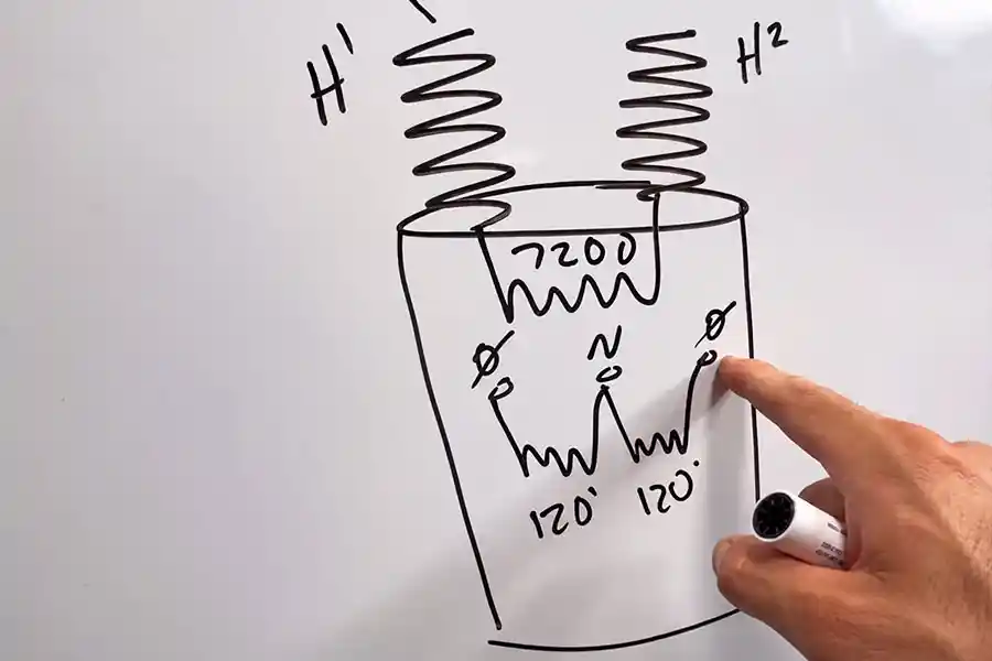
A 12.47 kV grounded-wye feeder may place about 7.2 kV across one phase-to-neutral winding.
This real-world engineering example shows: how to correctly specify a single-phase pole-mounted transformer stepping down a standard 12.47 kV overhead utility tap to residential split-phase power.
How Do You Find the Primary Winding Voltage?
Divide the line-to-line voltage by √3 for a balanced grounded-wye phase-to-neutral case.
Assume the project has:
- 12.47 kV grounded-wye distribution
- 12.47 kV line-to-line voltage
- About 7.2 kV phase-to-neutral voltage
- 120/240 V single-phase three-wire output
A nameplate marked 7200/12470Y – 120/240V may fit this system concept. The primary winding receives about 7.2 kV in the approved phase-to-neutral arrangement.
Do not turn this statement into a field connection instruction. The approved utility drawing controls the actual installation.
The current product table does not directly list a 7.2 kV primary. Therefore, do not call it a standard available model without factory confirmation.
What Else Must You Confirm After the Voltage?
Correct voltage is only one part of a complete transformer specification.
The project must still confirm:
- Required kVA
- Frequency
- 120/240 V center-tapped output
- Conventional or CSP design
- Bushing arrangement
- BIL
- Tap range
- Core option
- Ambient conditions
- Applicable standard
- Required tests
A buyer may correctly calculate 7.2 kV and still order the wrong unit. Missing load or protection data can change the design.
Frequently Asked Questions
Q1: How much does a single phase pole mount transformer cost?
The reference price for a 37.5kVA single-phase pole mounted transformer (EXW) from Huasheng factory is approximately $1800~$1950. The specific price depends on factors such as capacity (kVA), voltage level, and core material. You should contact the manufacturer directly for details. The overall estimated price range is $1700~$65000.
Q2: What are the different types of pole mounted transformers?
Pole mounted transformers are primarily categorized by phase count (single-phase vs. three-phase), protection design (Conventional vs. Completely Self-Protected), and core composition (CRGO silicon steel vs. amorphous metal).
Phase count (single-phase vs. three-phase), protection design (Conventional vs. Completely Self-Protected), and core composition (CRGO silicon steel vs. amorphous metal) are the main factors used to classify pole-mounted transformers.
- Single-phase vs. three-phase: Single-phase models dominate residential and rural taps. Three-phase overhead units (or banks of three single-phase units) power commercial motors and industrial sites.
- Conventional (CON) vs. CSP: Conventional units rely on external crossarm-mounted fuses and arresters. CSP units house internal weak-link fuses, secondary breakers, and tank-mounted arresters.
- CRGO vs. amorphous: CRGO silicon steel provides high saturation and low initial cost, while amorphous alloy ribbons cut no-load standby electrical losses.
Q3: How long does a single phase pole transformer last?
A well-selected unit may serve for decades, but no single lifespan fits every project.
A planning range of about 25 to 40 years is often discussed. It is not a warranty or fixed service-life promise.
Actual life depends on:
- Sustained overloading
- Ambient temperature
- Moisture entry
- Insulation aging
- Lightning and switching stress
- Protection coordination
- Maintenance
- Manufacturing quality
Compare temperature rise, losses, sealing, and test records. These facts are more useful than a broad lifespan claim.
Conclusion
Choosing the right single phase pole mounted transformer comes down to simple math and clear project specs. Start by checking your feeder connection and grounding to find the true primary winding voltage. Next, size your kVA using real peak demand rather than connected appliance wattage. Finally, balance your core losses, secondary split-phase wiring, and site conditions against IEEE or IEC standards. Getting these details right prevents premature failure, lowers electric waste, and keeps your power flowing reliably for decades.
Huasheng Transformer is a future leading single phase pole mounted transformer exporter in China. We supporting utility engineers, rural grid contractors, and international equipment distributors worldwide.
Related Article: