Power Distribution Transformer Solutions
Engineering SupportGlobal Project Supply

Three Phase Transformer Guide: Connections, Sizing, and Principles
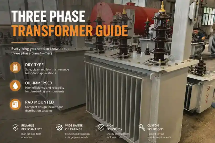
Three phase transformers are used a lot in utility grids. They are also used in industrial plants, commercial buildings, renewable energy projects, and other systems that carry large electrical loads. These transformer manufacturers need keep power networks stable and reliable.
Selecting one takes more than choosing a kVA rating. The primary and secondary voltage, frequency, connection, vector group, impedance, cooling method, and installation conditions must all work together.
This guide explains how three phase transformer work. It shows how Delta and Wye connections differ. It also explains how to calculate transformer capacity. It tells what information a manufacturer needs before making a technical offer.
Key Takeaways
- A three phase transformer works through electromagnetic induction.
- The winding connection affects the neutral, grounding arrangement, and phase displacement.
- Transformer capacity is rated in kVA.
- Three-phase transformers are available in oil-immersed, dry-type, and pad-mounted designs.
- Voltage and capacity alone are not enough for a quotation.
What Is a Three Phase Transformer?
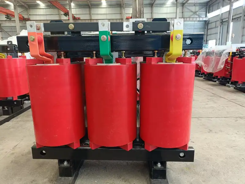
A three-phase transformer is a static electrical device that transfers power between three-phase AC circuits through electromagnetic induction.
A typical two-winding design has three primary windings and three secondary windings. The windings may share one three-phase magnetic core, or three separate single-phase transformers may be connected as a bank.
The transformer may perform one of two main jobs:
- A step-up transformer raises voltage for transmission or grid connection.
- A step-down transformer reduces voltage for distribution and end use.
For example, a renewable energy project may use a three-phase transformer to raise inverter output to the collection-grid voltage. An industrial plant may use one to reduce an 11kV utility supply to 400V or 415V.
A transformer does not convert DC to AC. An inverter or another power-electronic converter must perform that job before the transformer receives AC power. Refer to the Wikipedia entry on transformers.
How Does a Three-Phase Transformer Work?
A three-phase transformer uses changing magnetic flux to induce voltage in its secondary windings.
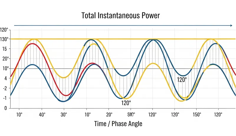
When a alternating Supply voltage is applied to the primary windings. it creates a dynamic magnetic flux. The three phase quantities are separated by 120 electrical degrees.
This field, oscillating at the system frequency. Induces an electromotive force (EMF) in the secondary windings. The changing flux then induces a secondary voltage according to Faraday’s law of electromagnetic induction.
In a balanced three-phase system, the combined instantaneous power is smoother than in a single-phase system. This supports steady motor torque and efficient transmission of larger loads.
How Do Electromagnetic Induction and the 120° Phase Relationship Work Together?
Each phase produces alternating flux, but the three flux waveforms do not reach their peaks at the same time. This feature makes three-phase distribution the global standard for heavy industrial loads. It is also standard for high-capacity distribution systems.
The phase displacement is:
- Phase A: reference position
- Phase B: 120° behind Phase A
- Phase C: 120° behind Phase B
This relationship gives a balanced system when the source, transformer, and loads are correctly configured.
How Does the Turns Ratio Change Voltage?
The voltage ratio is approximately equal to the winding turns ratio.
The basic relationship is:
V₁ ÷ V₂ ≈ N₁ ÷ N₂
Where:
V₁= primary winding voltageV₂= secondary windings voltageN₁= number of primary turnsN₂= number of secondary turns
A transformer with fewer secondary turns steps voltage down. One with more secondary turns steps voltage up.
Real output voltage also depends on load, impedance, tap position, conductor losses, and power factor.
A transformer does not convert DC into AC. A solar or battery system needs an inverter before AC power reaches the transformer.
How Is a 3 Phase Transformers Different from a Single Phase Transformer?
A 3 phase transformer is normally selected for three-phase loads and larger power systems. A single-phase transformer serves single-phase circuits and dispersed loads.
| Factor | Three-Phase Transformer | Single-Phase Transformer |
|---|---|---|
| Input power | Three-phase AC | Single-phase AC |
| Typical loads | Motors, production lines, commercial distribution, utility systems | Homes, lighting, small equipment, dispersed overhead loads |
| Power delivery | Smoother combined instantaneous power in a balanced system | Pulsating instantaneous power |
| Typical capacity | Common for medium and large loads | Common for smaller or dispersed loads |
| Motor operation | Suitable for three-phase motors | Cannot directly supply a standard three-phase motor |
| Conductors | Efficient for transmitting larger balanced loads | Suitable for smaller single-phase loads |
| Installation | Industrial, commercial, utility, and infrastructure systems | Residential, rural, and smaller services |
Three-phase equipment also has limitations:
- The protection and connection scheme is more complex.
- Phase sequence matters.
- Unbalanced single-phase loads can cause voltage and current imbalance.
- A wrong vector group can prevent safe parallel operation.
- A three-phase unit may be harder to transport than one small single-phase unit.
We usually recommend a three-phase transformer when the main load is three-phase, the power demand is high, or the site already uses a 3-phase distribution system. A single-phase transformer may be the better choice for small, dispersed, or single-phase loads.
Read Here, to Know more about single phase Transformer guide.
Which Three-Phase Transformer Connections Are Available?
The main connections are Delta–Delta, Delta–Wye, Wye–Delta, and Wye–Wye. Open-Delta is a setup with less capacity. It is used in certain situations.
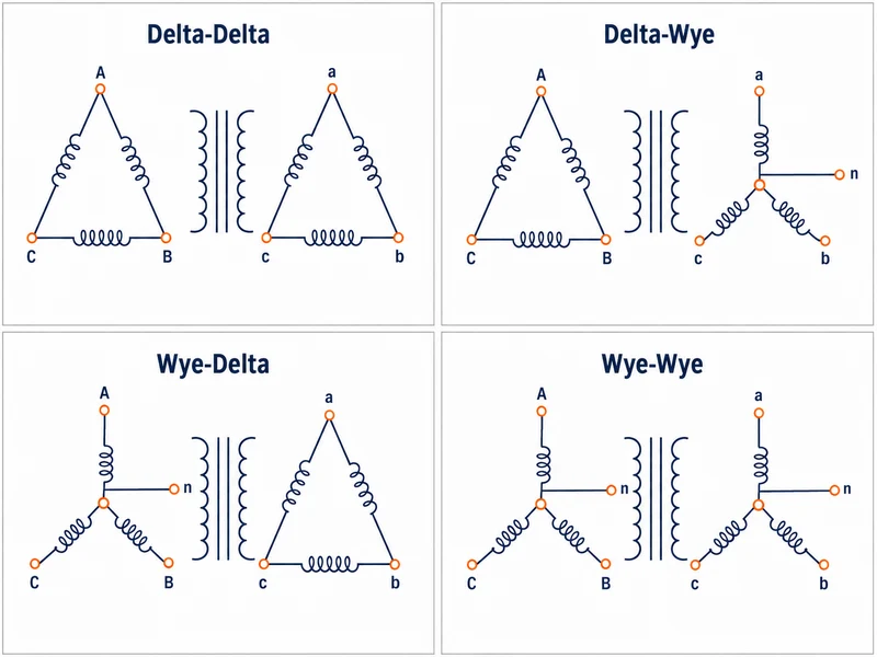
The delta connection is a closed loop. It gives great reliability for high-current, balanced loads. The Wye connection creates a common neutral point, making it the preferred choice for distribution systems.
| Connection | Secondary Neutral | Typical Phase Displacement | Common Use | Main Limitation |
|---|---|---|---|---|
| Delta–Delta | No | 0° | Three-phase industrial loads | No line-to-neutral supply |
| Delta–Wye | Yes, if brought out | 30° | Distribution systems and mixed loads | Vector group must match the network |
| Wye–Delta | No | 30° | Some step-up and industrial systems | No secondary neutral |
| Wye–Wye | Possible | 0° | Systems with coordinated grounding | Harmonics and neutral stability need review |
| Open-Delta | No in basic form | Connection-dependent | Temporary or limited-capacity service | About 57.7% of comparable Closed-Delta capacity |
Terminal markings, phase relationships, and connection details must match the project drawings and applicable requirements, such as IEEE C57.12.70
A closed Delta connection winding also provides an internal path for triplen harmonic currents. Wye can provide a neutral point for line-to-neutral loads when the neutral is brought out.
High-Leg Delta and Open Delta (V-V) Connections
A high-leg delta is a four-wire Delta secondary used in some North American installations. In a typical 240V system, the center-tapped winding provides 120V from two conductors to neutral, while the high leg measures about 208V to neutral. The high leg must not be used for 120V loads.
The Open Delta uses two transformers to produce three phase electric power. While this saves space and cost, it limits capacity to 57.7% of a standard bank. So it a “temporary” solution rather than a long-term primary distribution method.
Is a Winding Connection the Same as a Vector Group?
No. The connection describes the winding arrangement, while the vector group also identifies the neutral and phase displacement.
For example:
Delta–Wye:describes the basic connection.Dyn11: identifies a Delta high-voltage winding, a Wye low-voltage winding, a brought-out neutral, and a specific clock-hour displacement.
This matters when replacing or paralleling transformers. A similar voltage ratio does not prove that two units are compatible.
How Do You Size a Three Phase Transformers?
Transformer sizing is a precise task that balances current capacity with future growth potential. Start with the load, line voltage, current, and power factor. Then check starting current, harmonics, duty cycle, ambient conditions, and planned expansion.
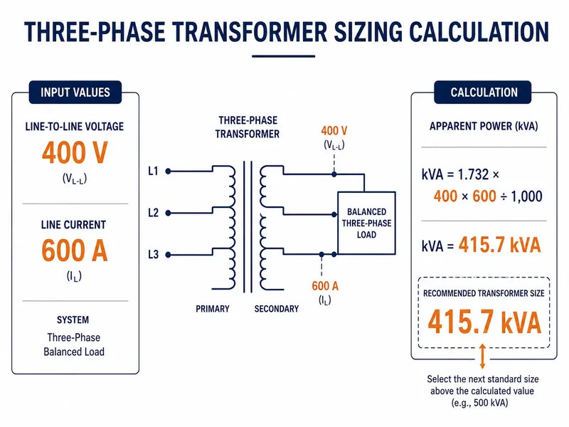
What Is the Three-Phase kVA Formula?
When line voltage and line current are known:
kVA = √3 × Line Voltage × Line Current ÷ 1,000
To calculate current:
Line Current = kVA × 1,000 ÷ (√3 × Line Voltage)
When kW and power factor are known:
kVA = kW ÷ Power Factor
Use line-to-line voltage and line current. These formulas assume a reasonably balanced three-phase load.
Calculating the Right kVA Rating and Full-Load Currents
A 400V balanced load drawing 600A requires about 415.7kVA before other design factors are considered. Based on the standard three-phase power equation defined in IEC 60076-1
Inputs:
- Line voltage: 400V
- Line current: 600A
- Balanced three-phase load
Calculation:
kVA = 1.732 × 400 × 600 ÷ 1,000
kVA = 415.7kVA
This is a calculated load, not a final transformer rating.
We do not apply one fixed 20% or 25% capacity margin to every project. A motor plant, data center, and commercial building do not have the same load profile.
Engineers must accurately distinguish between line voltage and phase voltage. Miscalculating line and phase voltage can lead to severe equipment damage or failure to meet the requirements of the connected load.
Accounting for Power Factor and Inrush Current
Per Schneider Electric’s Power Factor Technical Guide. A lower power factor requires more kVA and current to deliver the same kW load. This uses more of the transformer’s rated capacity. Additionally, engineers must consider inrush current—the temporary spike that occurs during startup. Failing to account for this can lead to nuisance tripping of protection relays.
Building in Overload Capacity and Future Load Growth
A transformer may operate at its rated capacity when the load, ambient temperature, cooling, and installation conditions meet its design requirements. Capacity margin should be based on the actual load profile and planned expansion, not a universal 80% rule.
How Should You Select a 3-Phase Transformers?
Confirm the electrical system, load, materials, site conditions, and required standards before selecting a transformer.
| Selection Factor | What to Confirm | Why It Matters |
|---|---|---|
| Capacity | Load, power factor, demand, starting method | Prevents undersizing or unnecessary oversizing |
| Voltage | Primary and secondary voltage | Determines the transformation ratio |
| Frequency | 50Hz or 60Hz | Affects magnetic flux and core design |
| Vector Group | Connection, neutral, phase displacement | Affects grounding and parallel operation |
| Impedance | Required percentage impedance | Affects fault current and voltage drop |
| Tap Range | Voltage adjustment range | Compensates for grid-voltage variation |
| Windings | Copper or aluminum | Affects cost, weight, size, and design |
| Core | CRGO or amorphous alloy | Affects no-load loss and cost |
| Cooling | ONAN, ONAF, AN, or AF | Affects rating and site requirements |
| Environment | Temperature, altitude, indoor or outdoor | Affects insulation and cooling |
| Standard | IEC, IEEE, utility specification | Controls design, testing, and acceptance |
Three factors often cause trouble.
Frequency: A transformer designed for 60Hz should not operate at the same rated voltage on 50Hz without an engineering review. Its volts-per-hertz value would rise by 20%, which could increase magnetic flux and overheating risk.
Vector group: Dyn11, Dyn1, and Yyn0 are not interchangeable. The required group must match the network and connected equipment.
Impedance: Lower impedance may reduce voltage drop but increase available fault current. Higher impedance may limit fault current but increase voltage drop. There is no universal “best” value.
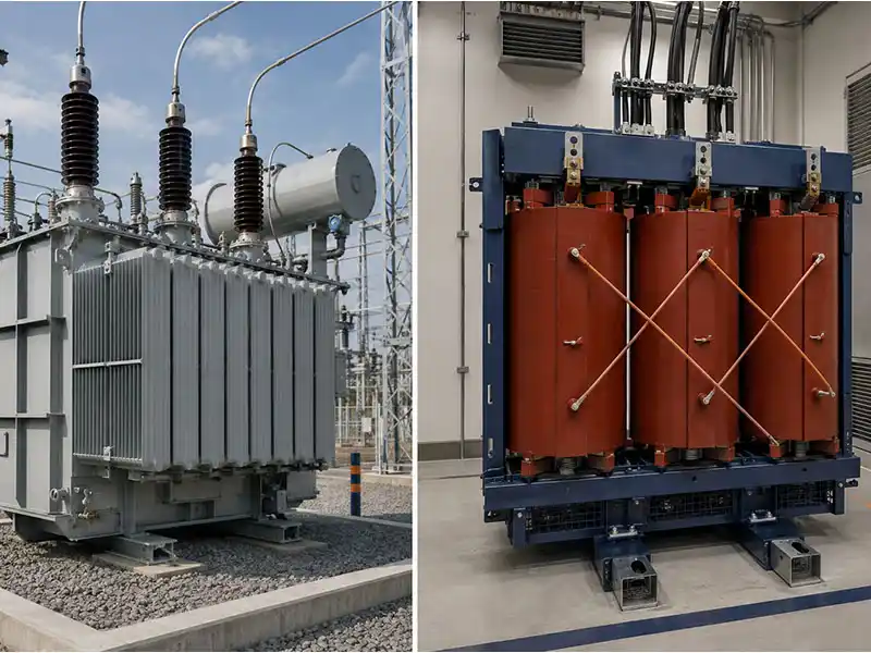
Choose Oil-Immersed or Dry Type 3-Phase Transformers?
Dry type transformers are the safest choice for indoor environments. They rely on air cooling and do not pose the fire risks associated with oil-filled units. For outdoor substations or high-load industrial applications, liquid-filled transformers are the industry standard. (Compliance with NEMA ST-20 standards)
Read Related Article: Oil Type Transformer for Distribution Projects: When Choice?
| Factor | Oil-Immersed | Dry-Type |
|---|---|---|
| Insulation | Insulating liquid and solid insulation | Solid insulation and air |
| Common location | Outdoor yards and substations | Indoor electrical rooms |
| Cooling | Commonly ONAN or ONAF | Commonly AN or AF |
| Fire planning | Liquid type, containment, and separation need review | No insulating-oil containment |
| Maintenance | Oil, seals, accessories, and cooling system | Cleanliness, ventilation, insulation, and fans |
| Common fit | Utility, industrial, renewable energy | Buildings, hospitals, transport, indoor industry |
Which Standards and Factory Tests Apply to Three-Phase Transformers?
The applicable standard depends on transformer type, market, voltage, purchaser specification, and the edition adopted by the project.
The IEEE C57 and IEC 60076 standards serve as the “law of the land” for transformer design and testing. A competent power systems engineer will always verify that a new installation meets these global benchmarks.
About more power distribution technical details standard, you need consult professional engineer.
| Standard or Code | Main Role | Typical Scope | Important Boundary |
|---|---|---|---|
| IEC 60076-1:2011 with applicable amendments | General transformer requirements | Power transformers | Other parts are needed for temperature rise, dielectric tests, sound, dry type, and other subjects |
| IEC 60076-2:2011 | Temperature rise | Liquid-immersed transformers | Does not replace dry-type requirements |
| IEC 60076-3:2013 with applicable amendments | Insulation levels and dielectric tests | Power transformers | Test levels depend on equipment voltage and specification |
| IEC 60076-11:2018 | Dry-type power transformers | Dry-type units within its stated scope | Not the general oil-immersed transformer standard |
| IEEE C57.12.00 | General requirements | Liquid-immersed distribution, power, and regulating transformers | Confirm the project-required edition |
| IEEE C57.12.01 | General requirements | Dry-type distribution and power transformers | Confirm voltage and product scope |
| NFPA 70, Article 450 | Installation and protection rules | U.S. electrical installations | The locally adopted NEC edition controls |
| Local grid code or utility specification | Network-specific requirements | Connection, losses, accessories, tests | May add requirements beyond IEC or IEEE |
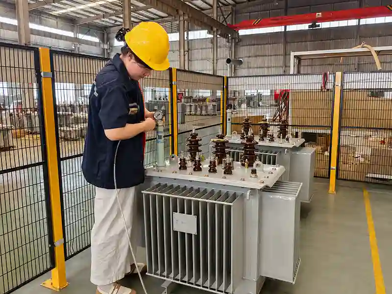
Common routine factory tests include:
- Winding resistance
- Voltage ratio
- Vector group or phase displacement
- No-load loss and No-Load Current
- Load loss
- Short-circuit impedance
- Applicable routine dielectric tests
- Tap Changer Checks
- Final visual and document inspection
Temperature-rise, impulse, partial-discharge, sound-level, and other tests may be type or special tests. They are performed when required by the standard or contract, not automatically on every transformer. View Huasheng’s Quality Control Process
Transformer Core Design and Construction
Successful transformer design is a synthesis of geometry, metallurgy, and thermal management. The physical architecture of the core dictates how the unit handles load fluctuations and heat.
Core Material: CRGO Silicon Steel and Magnetostriction
Modern transformers rely on Cold Rolled Grain Oriented (CRGO) silicon steel to maximize flux density while minimizing eddy current losses. However, the phenomenon of magnetostriction—the physical deformation of the steel under a magnetic field—remains a challenge. High-quality manufacturing makes sure the grain structure lines up perfectly. This lowers mechanical stress and cuts down the “hum” sound that shows poor build quality.
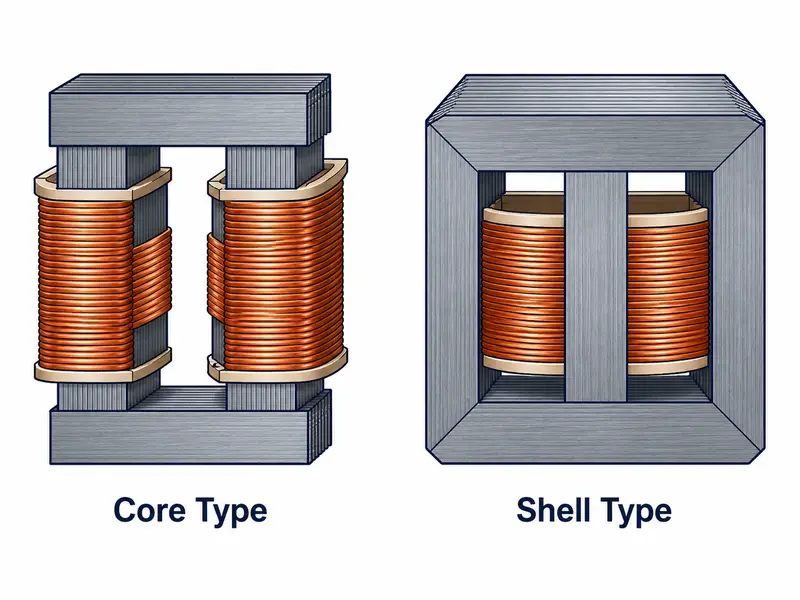
Core-Type vs. Shell-Type Transformer Designs
- Core-type transformers feature windings wrapped around the vertical limbs of the core. They are generally easier to cool and insulate, making them a common choice for high-voltage applications.
- Shell-type transformers surround the windings with core material. This provides superior mechanical bracing against short-circuit forces, though the design is more complex and difficult to repair.
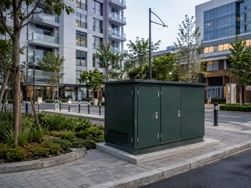
Where Are Three Phase Transformers Used?
3-phase transformers are used wherever a project needs to AC power transmission between voltage levels.
Common applications include:
- Utility and grid distribution
- Industrial facilities
- Commercial buildings
- Solar power projects
- Wind energy projects
- Transportation infrastructure
- Data centers
- Urban and residential distribution
What Selection Mistakes Should Buyers Avoid?
Most transformer selection problems start with missing load data, unclear system requirements, or assumptions copied from another project.
- Treating kW and kVA as the Same Value
Power factor must be included when converting real power into apparent power. - Ignoring Motor Starting Current
Running load alone may not show voltage-dip or heating problems. - Selecting the Wrong Vector Group
The voltage may look correct while the neutral or phase displacement is wrong. - Assuming 50Hz and 60Hz Are Interchangeable
A change in frequency changes volts per hertz and magnetic loading. - Ignoring Transformer Impedance
This can produce excessive fault current, poor voltage regulation, or bad load sharing. - Ignoring Harmonic Loads
VFDs, UPS systems, rectifiers, and inverters may create extra heating. - Comparing Quotations by kVA and Price Alone
Two transformers with the same voltage and capacity may differ in losses, impedance, materials, accessories, tests, and delivery scope.
What Should You Send a Three-Phase Transformer Manufacturer?
A good quotation needs electrical data, load information, site conditions, standards, accessories, and delivery scope.
Like capacity, primary voltage, secondary voltage, frequency, vector group, winding material, Tap range
If some details are missing, send us the load schedule, voltage, installation conditions, and single-line diagram first. We can identify which parameters still need confirmation.
Frequently Asked Questions
Q1: How Do You Calculate Three-Phase Transformer kVA?
Multiply line voltage by line current and √3, then divide by 1,000.
kVA = 1.732 × Line Voltage × Line Current ÷ 1,000
The formula gives the apparent load for a balanced system. The final rating must also account for power factor, starting current, harmonics, duty, and site conditions.
Q2: What Is the Difference Between Delta and Wye?
Delta connects the three windings in a closed triangle. Wye joins one end of each winding at a common point.
Wye can provide a neutral. Delta normally cannot. Their line and phase voltage relationships also differ.
Q3: Can a Three Phase Transformers Supply Single-Phase Loads?
Yes, if the secondary connection provides the required line-to-neutral or line-to-line voltage.
The load must be distributed across the phases to control imbalance. The neutral, grounding, conductor, and protection design must also be suitable.
Q4: Can a 60Hz Transformer Operate on a 50Hz System?
Not at its original rated voltage without an engineering review.
Operating a 60Hz design at the same voltage on 50Hz raises volts per hertz by 20%. That can increase core flux and cause saturation or overheating. As documented in Eaton’s Transformer Application Guidelines, this elevated V/Hz ratio increases core flux density, driving the core steel into magnetic saturation and causing thermal damage.
Q5: Which Parameters Are Needed for a Quotation?
Tell suppliers about transformer configuration. Provide capacity, primary and secondary voltage, frequency, vector group, impedance, tap range, transformer type, site conditions, standard, and quantity. A single-line diagram and load schedule will make the technical review more useful.
Conclusion
Mastering the three-phase transformer guide can help you project sucess. Whether you are a government procurement, EPC contractor, distributor, or engineer, you can read this guide.
Learn how magnetic flux and electromagnetic induction work together. Then they pick the right transformer design for industrial or renewable energy uses. You need handle delta connection setups carefully.
Husheng is a professional transformer suppliers, You can send problems to us.
References & Sources:
- International Electrotechnical Commission. IEC 60076-3:2013 — Power Transformers, Part 3: Insulation Levels, Dielectric Tests and External Clearances in Air.
- IEEE Standards Association. IEEE C57.12.00-2021 — General Requirements for Liquid-Immersed Distribution, Power, and Regulating Transformers.
- National Fire Protection Association. NFPA 70 — National Electrical Code.
If Have Project Questions, Contact Huasheng Experts: