Power Distribution Transformer Solutions
Engineering SupportGlobal Project Supply

Padmount Transformer Buying Guide: Types, Sizing, Specifications
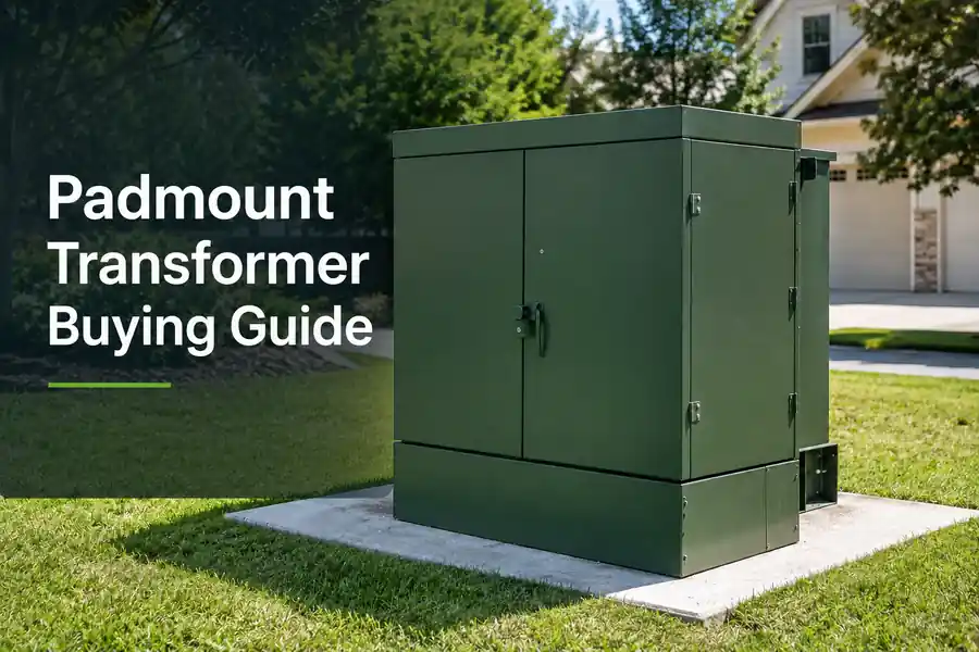
Buying a padmount transformer by kVA alone is a costly mistake. Two units can share the same capacity and still have different voltages, bushings, feed systems, protection devices, losses, and installation needs.
A pad mount transformers is an oil-filled distribution transformer installed on a concrete pad. It connects to an underground medium-voltage network. A locked steel cabinet protects the high-voltage and low-voltage terminals.
It can be single-phase or three-phase. Buyers must also choose between radial feed and loop feed. Dead front and live front, and several voltage and protection options.
This guide walks you through the selection process, capacity calculations, specification writing, and supplier comparison.
This guide explains each choice. It also shows how to size the transformer, read the main specifications, prepare the site, compare quotations, and send a clear RFQ.
What Is a Padmount Transformer?
A padmount transformer is a locked steel box on a concrete pad. It steps down medium-voltage electricity from underground cables to usable low-voltage power. Ideal for homes, commercial buildings, campuses, hospitals, and industrial equipment
It has a sealed oil tank and lockable high-voltage and low-voltage compartments. It’s designed for underground distribution systems—not for overhead lines.
You can also call this product an oil-filled padmount transformer. It also differs from a compact substation.
Before you go any further: figure out if your project uses underground cables or overhead lines. If it’s overhead, you probably need a pole-mounted transformer. Get this wrong and nothing else matters.
How Does a Padmount Transformer Work?
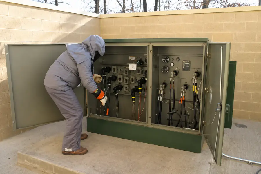
Underground medium-voltage cables bring power into the high-voltage side of the transformer. Bushings, fuses, switches, and other devices connect and protect the circuit.
The core and windings then reduce the voltage. Low-voltage bushings carry power to the building, service panel, or distribution board.
What you do need to know. Confirm Your primary voltage, secondary voltage, and terminal arrangement. Then to get your quote accurately with supplier.
Padmount Transformers Types and Configurations
The main choices are phase, feed arrangement, and high-voltage interface. A buyer may need a single-phase or three-phase unit, a radial-feed or loop-feed layout, and a dead-front or live-front design.
These choices solve different problems. They should not be treated as three names for the same feature.
Each choice affects what the transformer can handle, power reliable, connections types, and costs.
Single-Phase Padmount Transformers
Single-phase units are for residential underground distribution and small commercial loads. They’re simpler and cheaper than three-phase units, but they can’t handle big commercial or industrial loads.
Huasheng single-phase padmount transformers range from 25 to 250 kVA. Primary voltage options include 7.62 kV and 19.92 kV. Secondary voltage is typically 120/240 V. Tap range is usually ±2 × 2.5%. CRGO steel core is standard.
Typical standard-design data include:
| Rating (kVA) | No-Load Loss (W) | Load Loss (W) | Approx. Total Weight (kg) |
|---|---|---|---|
| 25 | 115 | 420 | 405 |
| 37.5 | 130 | 520 | 423 |
| 50 | 150 | 660 | 459 |
| 75 | 190 | 980 | 557 |
| 100 | 245 | 1,230 | 697 |
| 167 | 380 | 1,560 | 925 |
| 250 | 550 | 2,000 | 1,215 |
These figures are design examples. Final losses, dimensions, accessories, and weights must match the approved technical data sheet.
A small business does not always need a single-phase unit. The local supply system and actual load decide that.
Read Related Article: Single Phase Transformer Buying Guide.
Three-Phase Padmount Transformers
A three-phase padmount transformer supplies larger or balanced three-phase loads. Common uses include commercial buildings, factories, hospitals, universities, data centers, pumps, and renewable energy projects.
Three-phase padmount transformers range from 75 to 2,500 kVA (and sometimes up to 10 MVA under IEEE C57.12.34). Primary voltage options go from 7.2 kV up to 34.5 kV. Secondary voltage options range from 120 V to 600 V. Tap range is typically ±5% or ±2 × 2.5%. Common vector groups include Dyn11. Impedance examples are 5.5% or 6%.
The supplied product data show these design options:
- Rated capacity: 75–2,500 kVA
- Primary voltage examples: 7.2–34.5 kV
- Low-voltage options: 120–600 V
- Tap range: ±5% or ±2 × 2.5%
- Vector group example: Dyn11
- Impedance examples: 5.5% or 6%
The table below gives four design examples:
| Capacity | No-load loss | Load loss at 75°C | Impedance | Dimensions |
| 75 kVA | 180 W | 1,250 W | 5.5% | 1550 × 1170 × 1750 mm |
| 500 kVA | 680 W | 5,100 W | 5.5% | 1650 × 1470 × 1750 mm |
| 1,000 kVA | 1,150 W | 10,300 W | 5.5% | 1850 × 1550 × 1950 mm |
| 2,500 kVA | 2,680 W | 27,786 W | 6% | 2050 × 1950 × 2150 mm |
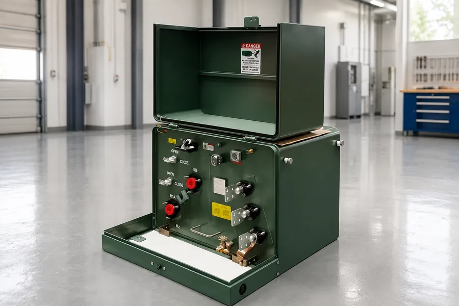
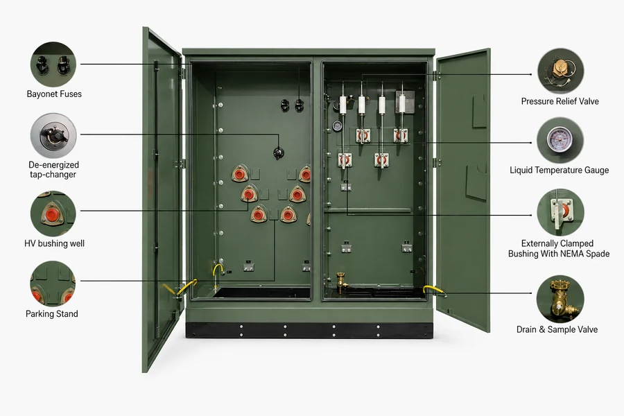
Look for these components on a real unit: Bay-O-Net fuse, tap changer, HV bushing well, pressure relief valve, and drain/sample valve.
Critical reminder: voltage combination, vector group, impedance, and accessories all depend on your project’s specific data sheet. Must confirm with supplier.
How Do You Choose Between Single-Phase and Three-Phase?
Choose the phase that matches the supply system and connected load. Do not choose by building type alone.
| Factor | Single-Phase | Three-Phase |
|---|---|---|
| Supply system | Single-phase distribution | Three-phase distribution |
| Typical load | Residential, small commercial | Commercial, industrial, institutional |
| Capacity range | 25–250 kVA | 75–2,500 kVA (up to 10 MVA) |
| Secondary voltage | 120/240 V | 120–600 V |
| Common applications | Homes, small stores, street lighting | Hospitals, universities, factories, data centers |
| Project complexity | Lower | Higher |
A hospital often uses three-phase power, but that does not prove which transformer it needs. The buyer must still confirm voltage, load, redundancy, and protection. Learn Commercial Building Transformer Solutions.
Read Related Article: Three Phase Transformer Guide.
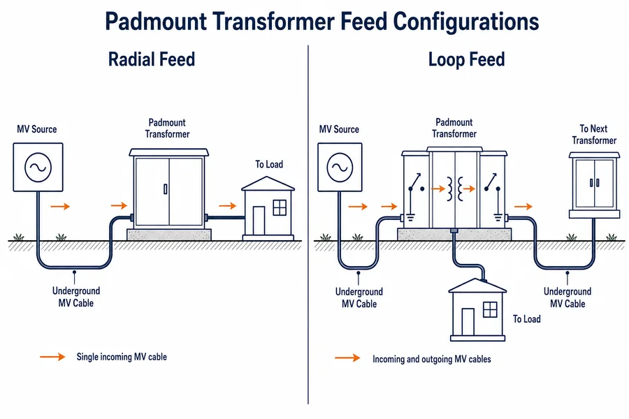
Radial-Feed vs. Loop-Feed Padmount Transformers
Radial feed has one power path. Loop feed lets power continue to the next device and offers more flexible isolation and restoration.
Here’s the breakdown:
- Radial feed: one incoming cable, one path. Simpler, cheaper. If the cable fails, everything downstream loses power.
- Loop feed: two cables—one in, one out to the next transformer. You can isolate a fault and keep the rest of the loop running.
A loop-feed design has additional cable connections. So it costs more upfront but gives you better reliability. The right choice depends on your grid topology and what your utility requires.
Dead-Front vs. Live-Front Designs
A dead-front design uses insulated, separable high-voltage connectors. Live-front means you can see exposed metal parts when you open the cabinet.
In a dead-front design, the high-voltage connections are inside shielded rubber elbow connectors. You can open the cabinet and not see any “hot” metal. The bushing is fully insulated with rubber, nylon resin, or epoxy. The cable connects via an elbow.
In a live-front design, the conductor where the terminal connects is exposed. You see porcelain or epoxy bushings with metal spade terminals.
Dead-front is safer—lower risk of arc flash, lower risk of accidental contact. Live-front is older technology, still used in controlled-access areas and temporary applications. Most new installations use dead-front.
One more thing: the interface must be compatible with your cables, elbows, and utility requirements.
How to Size a Padmount Transformer
Size the transformer from the real electrical load, not from floor area or a rough equipment count. The calculation must consider voltage, current, power factor, motor starting, load pattern, and future growth.
A load schedule gives the best starting point. A guess gives the supplier very little to work with.
Calculate the Required kVA
Use voltage and current to calculate the base apparent power.
For a single-phase load:
kVA = V × A ÷ 1,000
For a three-phase load:
kVA = √3 × line voltage × line current ÷ 1,000
If the load is given in kW:
kVA = kW ÷ power factor
Example (three-phase): You have a load drawing 200 amps at 480 volts. kVA = 1.732 × 480 × 200 ÷ 1,000 = 166 kVA. Round up to the next standard size—probably 225 kVA.
Send your load schedule and we’ll help verify the capacity.
Check Load Type, Power Factor and Future Growth
Motors, compressors, pumps, welders, UPS systems, VFDs, and nonlinear loads all affect your transformer differently.
- Motors have high starting current—sometimes 6–8 times full load.
- Nonlinear loads (UPS, VFDs, LED drivers) create harmonics that can cause extra heating.
- Power factor below 0.85 means you need more kVA for the same kW.
Future growth should be based on actual expansion plans, not a random 20% buffer. Ask the facility manager what’s coming in the next 5–10 years.
Provide: largest motor kW and starting method, UPS/VFD information, and load profiles.
When Do Temperature and Altitude Require Derating?
High temperature, high altitude, or restricted cooling may reduce the transformer’s usable capacity.
Air density falls at high altitude. This can affect heat removal and insulation coordination. High ambient temperature also leaves less room for temperature rise.
An undersized transformer may run hot and suffer poor voltage performance. A much larger unit costs more and may spend years at a very low load.
There is no single derating percentage for every project. Provide the altitude, temperature range, and installation conditions for review.
Key Specifications and Applicable Standards
Lock down these specs before you ask for a quote: capacity, voltage, frequency, phase, connection type, impedance, losses, insulating liquid, feed structure, accessories, standards, and installation environment.
Let’s go through each one.
Primary Voltage, Secondary Voltage, Frequency and Connections
Primary voltage is what comes in from the utility. Secondary voltage is what you need for your equipment. Don’t write “medium voltage”—give the actual number (e.g., 13.8 kV, 480 V).
Also specify:
- Frequency: 50 Hz or 60 Hz
- Connection: Delta or Wye
- Neutral: grounded or ungrounded
- Vector group: e.g., Dyn11 (this is just an example—not all three-phase units use Dyn11)
Impedance, Fault Current and Protection Coordination
Impedance affects voltage regulation and available fault current. It also determines how your upstream and downstream protection devices coordinate. (Refer Yale Padmount Design Standard)
- Higher impedance = better fault current limiting, but worse voltage regulation.
- Lower impedance = better regulation, but higher fault currents.
Typical impedance for padmount transformers is 5.5% to 6%—but the final value must be confirmed on the approved data sheet. (Data From Electric System Approved Materials Manual)
If you’re an EPC: provide your short-circuit calculation or protection requirements. Don’t let the factory guess.
No-Load Loss, Load Loss, Temperature Rise and Sound
No-load loss happens 24/7, even when the transformer isn’t powering anything. Load loss varies with how much current you’re drawing.
When comparing quotes, make sure you’re comparing:
- Same kVA rating
- Same reference temperature (usually 75°C)
- Same standard
Don’t accept “low loss” or “low noise” without data sheet numbers or test reports.
Ask for guaranteed loss values and routine test reports.
Windings, Insulating Liquid, Terminals and Protection
Copper vs. aluminum windings: copper is more conductive but heavier and more expensive. Aluminum is lighter and cheaper but needs larger cross-sections. Neither is automatically “better”—it depends on the design.
Insulating liquid:
- Mineral oil: standard, lower cost, fire point ~165°C
- Natural ester (vegetable-based): biodegradable, non-toxic, fire point >360°C. Better for environmentally sensitive areas or near occupied buildings. FR3 is a common brand.
Accessories to specify:
- Bay-O-Net fuse
- Load-break switch
- Tap changer (off-circuit or on-load)
- Pressure relief device
- Temperature indicator
- Liquid level indicator
- Drain and sample valve
IEEE, IEC and Project-Specific Requirements
Common references may include:
- IEEE C57.12.00 – General requirements for liquid-immersed transformers
- IEEE C57.12.34 – Pad-mounted, three-phase, 10 MVA and smaller
- IEEE C57.12.38 – Pad-mounted, single-phase, 250 kVA and smaller
- IEEE C57.12.28 – Enclosure integrity
- IEEE C57.12.90 – Test code
- IEC 60076 – Power transformer standard (international)
- NEC Article 450 for parts of a US installation
A standard may cover the transformer, enclosure, tests, or site installation. These are not the same scope. Confirm which rules govern the equipment and which govern the site. ( From IEEE Standard Requirements for Padmount transformer)
Padmount Transformers vs. Other Distribution Solutions
Choose padmount for underground distribution with locked ground-level equipment. Choose pole-mounted for overhead lines. Consider compact substation if you need integrated switchgear.
Padmount Transformer vs. Pole Mounted Transformer
| Factor | Padmount | Pole-Mounted |
|---|---|---|
| Location | Ground level on concrete pad | On a utility pole |
| Line type | Underground cables | Overhead lines |
| Capacity | Up to 10 MVA | Typically up to 500 kVA |
| Safety | Lockable, tamper-resistant enclosure | Accessible from ground, requires climbing |
| Footprint | Requires concrete pad and clearance | Minimal ground footprint |
| Maintenance | Ground-level access | Requires bucket truck or climbing |
If your site has underground utilities, you need a padmount. If you have overhead lines, you probably need a pole mounted Units.
See the Pole Mounted Transformers range for that product type.
Padmount Transformer vs. Compact Substation
Padmount = transformer with lockable terminal compartments. Compact substation = transformer + high-voltage switchgear + low-voltage distribution panels in one package.
- Padmount: just the transformer. You provide your own switchgear and distribution panels elsewhere.
- Compact substation: all-in-one. Includes MV switchgear, transformer, and LV distribution. Bigger footprint, higher cost, faster installation.
Tell your supplier whether you need high-voltage switchgear and low-voltage distribution included. Otherwise, you’ll get quotes for completely different products.
What Must Be Checked Before Installation?
The foundation drawing, cable entry points, and clearance distances must be approved before you pour concrete. Even if the electrical specs are perfect, the transformer might not fit.
What Should the Foundation Drawing Show?
The foundation drawing should show the transformer footprint, pad opening, cable entry, grounding point, and cabinet orientation.
Check these items before pouring concrete:
- Overall length and width
- Base channel or mounting points
- High-voltage cable opening
- Low-voltage cable opening
- Door opening direction
- Grounding connection
- Lifting access
- Service access
Use the approved drawing, not a general brochure size. Custom accessories can change the final dimensions.
How Much Clearance and Service Space Are Needed?
The required space depends on the equipment drawing, utility rules, local code, and site risk.
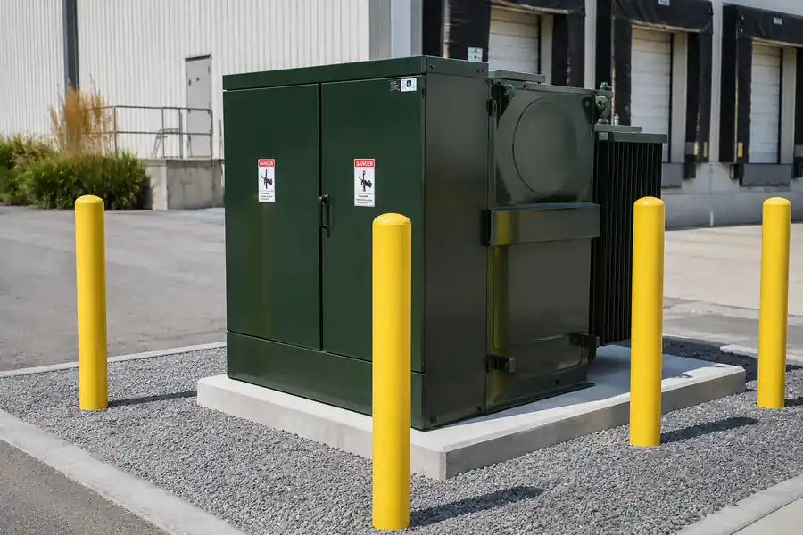
The doors must open fully. Workers need safe access. The site may also need airflow, lifting space, drainage, bollards, or vehicle protection. (Data from Ryan Electric Minimum Clearance)
- Front (access side): at least 10 feet (3 meters) for utility workers
- Sides and rear: at least 3 feet (0.91 meters) for ventilation and maintenance
- From buildings: at least 3 feet from non-combustible walls, more from combustible
- Overhead: no obstructions within 12 feet (3.66 meters)
What Should Be Checked Before Energization?
Qualified personnel should check the grounding, oil condition, connections, tap position, protection, nameplate, and cables before energization.
The review may include:
- Visible leaks or shipping damage
- Liquid level
- Grounding connections
- Cable and bushing condition
- Tap-changer position
- Fuse and switch configuration
- Phase sequence
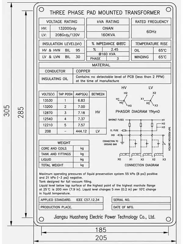
- Nameplate against approved drawings
- Required test documents
This is high-voltage equipment. These checks are not DIY instructions. Where applicable in the United States, work on electric power generation, transmission, and distribution equipment should follow the safety requirements in OSHA 1910.269 and be performed by qualified personnel.
What Can a Drawing Error Cost?
A drawing error can cost more than the discount gained from a cheaper transformer.
Imagine that the cable opening does not match the foundation. The project may need concrete rework, a second crane visit, new cable parts, and several days of delay.
That is a cost-risk example, not a claimed customer saving. A real case should show the project facts, the error, the correction, and the cost calculation.
Early drawing approval is much cheaper than site rework.
What Must Be Checked When Replacing an Old Unit?
The old nameplate, footprint, cable openings, bushings, terminals, and impedance must be checked before a replacement transformer is selected.
Send the supplier:
- A clear nameplate photo
- Primary and secondary voltage
- Rated capacity and frequency
- Phase and impedance
- Overall dimensions
- Foundation and cable-entry dimensions
- Radial-feed or loop-feed arrangement
- Bushing and cable-elbow details
- Low-voltage terminal layout
- Photos of the unit and surrounding site
The same kVA rating does not mean the new transformer will be a drop-in replacement. It may match the electrical load but fail to fit the existing pad, cables, or connectors.
What Are Common Problems with Padmount Transformers?
Common issues: overheating or overloading, oil leaks, moisture ingress, corrosion, bushing and connection problems, fuse operations, and grounding or enclosure issues.
What Causes Overheating and Voltage Problems?
Overheating may come from overload, a loose connection, poor cooling, load imbalance, or an internal fault.
Possible causes:
- Load exceeds rated capacity
- Poor ventilation (blocked by vegetation, debris, or nearby structures)
- Loose connections causing local heating
- Unbalanced loads causing one phase to overheat
Action: check actual load currents, thermal imaging results, and ventilation. Don’t diagnose remotely—get someone on site with a thermal camera.
What Causes Oil Leaks, Moisture, and Corrosion?
Oil leaks come from failed gaskets, damaged tank welds, or mechanical impact. Moisture gets in through leaks or poor seals. Corrosion happens in coastal or industrial environments. Insulation aging accelerates with heat and moisture.
Check where the leak starts and whether the liquid level has fallen. Water around the cabinet may also come from poor site drainage, not the transformer.
Why Do Bushings, Fuses, and Switches Fail?
These parts may fail because of age, contamination, loose connections, downstream faults, or poor protection coordination.
A fuse that operates again after replacement needs investigation. Fitting a larger fuse without a protection study can create a bigger risk.
Take clear photos of the bushing, fuse, switch, and nameplate. Include the fault record and connected load when asking for technical support.
Should You Repair or Replace the Transformer?
Repair may suit a local seal, fitting, bushing, or connection problem, while major insulation or tank damage may require replacement.
| Situation | Likely Action |
|---|---|
| Minor accessory issue (fuse, gauge, valve) | Repair |
| Seal or gasket leak | Repair |
| Major insulation damage | Replace |
| Tank deformation or severe corrosion | Replace |
| Capacity no longer sufficient | Replace |
| Old unit with obsolete interfaces | Replace |
| Frequent failures | Replace |
Repair is cheaper in the short term. Replace makes sense when the unit is old, damaged, or no longer meets your needs.
Send the nameplate, year, fault records, test reports, and site photos for a replacement assessment.
Padmount Transformer Cost, Lead Time and Warranty
The price depends on the complete specification, not just the kVA rating.
There’s no single price. Capacity, voltage, winding material, insulating liquid, feed type, accessories, standards, testing, and shipping all change the final cost
What Changes the Transformer Price?
Capacity, voltage, materials, accessories, and project standards are the main price drivers.
A custom-built padmount transformer may cost more than a basic standard design. Special interfaces, natural ester, copper windings, extra tests, and custom paint can also add cost.
- kVA rating – bigger = more expensive
- Voltage class – higher voltage = more insulation = more cost
- Winding material – copper costs more than aluminum
- Insulating liquid – natural ester costs more than mineral oil
- Feed type – loop feed costs more than radial
- Accessories – more features = higher cost
- Special testing – additional tests add cost
- Customization – non-standard designs cost more
Typical range: a single-phase units start FOB around $20,000–$34,000. Larger three-phase units can go above $30000-45,000.
Don’t rely on these numbers for your budget. Get a quote with your actual specifications.
Freight, Landed Cost and Production Lead Time
Your total cost isn’t just the transformer price. Consider:
- Packaging (export crating)
- Inland transportation (factory to port)
- Ocean freight
- Insurance
- Destination port charges
- Customs and duties
- Site delivery and offloading
- Spare parts
Lead time breaks down into:
- Engineering/drawing approval
- Material procurement
- Production
- Testing
- Shipping
Don’t accept a single “total days” number. Ask for each phase separately.
Provide destination port, Incoterm, quantity, and site offloading conditions.
What Should a Padmount Transformer Warranty Cover?
The warranty should state its period, start date, covered defects, exclusions, claim process, and remedy.
Ask these questions:
- Does the warranty start at shipment, delivery, or energization?
- Which parts are covered?
- Are site labor and freight included?
- What documents are needed for a claim?
- What happens if misuse or poor installation caused the fault?
- Are spare parts available?
- How fast will the supplier respond?
A clear padmount transformer warranty is more useful than a long promise with no written scope.
Frequently Asked Questions
Q1: How Long Does a Padmount Transformer Last?
There is no fixed life for every unit. Load, temperature, insulation condition, moisture, maintenance, faults, and the site environment all matter. Use operating records, oil tests, and electrical tests to judge an older transformer.
Q2: Can a Padmount Transformer Be Installed Indoors?
Padmounts are designed for outdoor use. Indoor installation requires separate review of insulating liquid, fire protection, ventilation, space, and local codes. Don’t assume it’s allowed just because the datasheet says “indoor/outdoor.”
Q3: Should a Failed Padmount Transformer Be Repaired or Replaced?
Minor accessory or seal issues can be repaired. Major insulation damage, structural corrosion, insufficient capacity, or obsolete interfaces usually mean replacement. The decision requires on-site inspection and testing.
Q4: Does a Padmount Transformer Need a Fence?
A locked, tamper-resistant cabinet does not remove every site protection rule. The utility or local authority may still require clearances, bollards, fencing, or traffic protection based on the site.
Conclusion
The right purchase depends on capacity, voltage, phase, feed type, interface, impedance, standard, and site conditions. Get these right and the rest falls into place.
What Should You Remember?
The safest purchase starts with system data, not a model number.
- Match the phase to the supply system and load.
- Calculate kVA from real demand.
- Confirm voltage, frequency, connection, and impedance.
- Choose radial or loop feed from the network design.
- Match dead-front or live-front interfaces to the cable system.
- Approve the foundation drawing before civil work.
- Compare losses, accessories, tests, freight, and warranty.
- Send the nameplate and site photos for replacement projects.
- Compare supplier scope, not price alone.
Related Read Article:
Huasheng is a professional Distribution Transformer Manufacturers, You can send problems to us. If Have Project Questions, Contact Huasheng Experts: